Framework represents a fundamental shift in laptop design philosophy, prioritizing user repairability, upgradeability, and long-term sustainability over disposable technology. Unlike traditional laptops that become obsolete due to soldered components, the Framework 13 is designed to evolve with your needs.
Strong demand in environmentally conscious markets
Collector interest in early generation models
Documentation Benefits:
Repair history increases buyer confidence
Upgrade documentation justifies premium pricing
Component quality can be verified
Remaining warranty transferable
🚀 Getting Started with Framework Upgrades
First Steps:
Identify your current configuration
Determine your upgrade goals and budget
Research compatible components
Gather necessary tools
Recommended Initial Upgrades:
RAM expansion for better multitasking
SSD upgrade for faster storage
Expansion cards tailored to your workflow
Input cover customization
2. Essential Toolkit for Framework 13 Upgrades
🛠️ Framework's Tool-Included Advantage
Unlike traditional laptops, Framework includes the essential magnetic screwdriver with every laptop, embodying their commitment to repairability. This section covers both the included tools and recommended additions for comprehensive upgrades.
📦 Included with Your Framework 13
Framework Magnetic Screwdriver:
Custom-designed Phillips #0 bit
Magnetic tip for easier screw handling
Right-sized for all Framework screws
Ergonomic handle for comfortable use
Expansion Card Removal Tool:
Small plastic tool for safe card removal
Prevents damage to card connectors
Stored in expansion card slots when not in use
🔧 Essential Upgrade Toolkit
Tool
Purpose
Framework-Specific Notes
Recommended Product
Phillips #0 Screwdriver
All disassembly screws
Framework includes one, but having a spare is useful
Framework included or iFixit Phillips #0
Spudger Set
Prying and connector removal
Plastic only to avoid damaging components
iFixit Spudger Set
Tweezers
Handling small connectors
Non-magnetic recommended
ESD-safe anti-magnetic tweezers
Anti-Static Wrist Strap
ESD protection
Critical for motherboard work
Any ESD-safe wrist strap
Magnetic Project Mat
Screw organization
Framework screws are similar but different lengths
Unlike traditional laptops that require complete disassembly for basic upgrades, the Framework 13 features a dedicated bottom cover that provides direct access to the most commonly upgraded components: RAM, SSD, and WiFi card. This thoughtful design exemplifies Framework's commitment to repairability.
🔩 Bottom Cover Fastener System
Screw Location
Type
Quantity
Special Features
Notes
Corner Screws
Phillips #0
4
Captive design
Will not fully remove from chassis
Edge Screws
Phillips #0
4
Captive design
Will not fully remove from chassis
Center Screw
Phillips #0
1
Standard removal
Comes completely out
🔧 Step-by-Step Removal Process
Preparation:
Ensure laptop is powered off and disconnected from power
Remove all expansion cards from sides
Place laptop on clean, soft surface
Gather Framework screwdriver and plastic opening tools
Screw Removal Sequence:
Start with the center screw (only one that removes completely)
Loosen the 8 captive screws in diagonal pattern
Turn counterclockwise until screws stop turning (2-3 full turns)
Do not force screws - they should stop naturally when fully loosened
Cover Release:
Start at front edge near touchpad
Gently lift with plastic tool or fingernail
Work around perimeter, releasing clips every 2-3 inches
Lift cover straight up once all clips are released
⚙️ Framework's Captive Screw Advantage
No Lost Screws:
Screws remain in chassis when loosened
Eliminates risk of losing small components
Simplifies reassembly process
Prevents incorrect screw placement
Damage Prevention:
Prevents over-tightening and strip damage
Ensures proper alignment during reassembly
Maintains consistent pressure distribution
Reduces risk of cross-threading
🚧 Common Challenges & Solutions
Stubborn Clips:
Use plastic opening tool instead of metal
Work slowly around perimeter
Apply gentle, even pressure
If stuck, check for missed screws
Tight Screws:
Ensure using proper Phillips #0 screwdriver
Apply downward pressure while turning
If stripped, use rubber band for extra grip
Never force - seek help if resistance continues
Alignment Issues:
Check for obstructions or cables in the way
Verify all screws are fully loosened
Ensure expansion cards are removed
Check for debris in screw holes
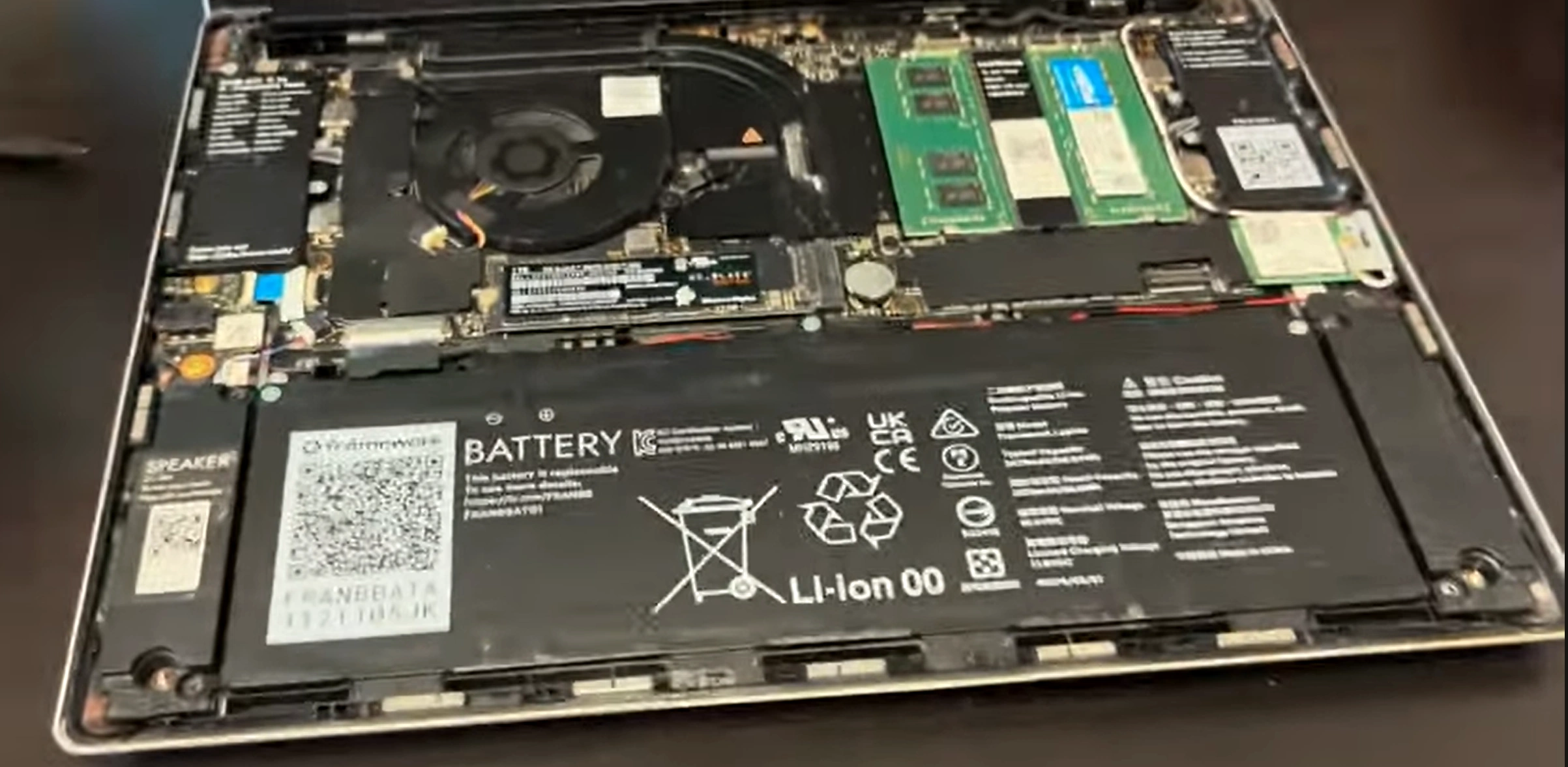
🔍 Immediately Accessible Components
RAM Slots:
Two DDR4 SODIMM slots
Easy upgrade access
No additional disassembly required
Storage:
M.2 2280 SSD slot
Single screw retention
Various SSD lengths supported
Wireless Card:
Intel AX210 WiFi 6E (typically)
Two antenna connections
Standard M.2 form factor
Battery Connector:
Easy access for disconnection
Clearly marked connector
Safety disconnect for further work
⚠️ Safety Precautions
Disconnect battery before working on internal components
Use anti-static precautions when handling components
Handle components by edges only
Keep screws organized for reassembly
Avoid touching gold contacts on components
Work in clean, dry environment
🔁 Reassembly Instructions
Ensure all internal work is completed
Verify no tools or debris left inside
Align bottom cover properly with chassis
Press down evenly until all clips engage
Start with center screw and tighten securely
Tighten captive screws in diagonal pattern
Ensure cover sits flush with no gaps
Reinstall expansion cards
💡 Immediate Upgrade Opportunities
RAM Upgrades:
Up to 64GB DDR4 (2x32GB)
3200MHz recommended speed
No additional disassembly required
Storage Upgrades:
Single M.2 2280 slot
PCIe 4.0 compatible
Up to 4TB+ capacity supported
WiFi Upgrades:
Intel AX210 WiFi 6E standard
Future WiFi 7 compatibility possible
Easy antenna connection system
🔍 Troubleshooting Common Issues
Cover Won't Sit Flush:
Check for missed clips around perimeter
Verify no cables are trapped under edges
Ensure all screws are properly loosened
Screw Won't Tighten:
Check for stripped threads
Verify correct screw type and length
Ensure proper alignment with chassis
Gaps After Reassembly:
Check clip alignment around perimeter
Verify all screws are proper tightness
Ensure no damage to mating surfaces
🛠️ Maintenance Tips
Cleaning Opportunity:
Clean dust from fans and heatsinks while open
Use compressed air for thorough cleaning
Check for debris in ventilation areas
Inspect thermal paste condition if visible
Preventative Maintenance:
Check battery health in BIOS
Verify all connections are secure
Inspect for signs of wear or damage
Document component conditions for future reference
Use plastic tools to gently pry bezel starting from bottom edge
Work around perimeter slowly and carefully
Release all clips before attempting to remove
Set bezel aside on clean surface
Display Removal:
Apply suction cup to center of screen
Gently lift to access display cable
Disconnect eDP cable (lift locking flap first)
Remove 4-6 mounting screws around display edges
Lift display assembly out carefully
New Display Installation:
Clean adhesive residue from chassis
Position new display in chassis
Secure with mounting screws
Connect eDP cable and secure locking mechanism
Test display before applying adhesive
Bezel Installation:
Apply new adhesive tape to bezel or chassis
Align bezel properly with camera and sensors
Press firmly around entire perimeter
Ensure all clips engage properly
🔌 eDP Connector Details
Connection Specifications:
40-pin eDP connector
Locking mechanism (flip-up style)
Right-angle connection
Standard 0.5mm pitch
Handling Precautions:
Disconnect battery before handling
Use tweezers for locking mechanism
Avoid bending pins
Ensure complete seating before locking
📏 Adhesive Application Guide
Adhesive Types:
Pre-cut adhesive strips (recommended)
Double-sided tape (1mm width)
Liquid adhesive (not recommended)
Frame-style adhesive gaskets
Application Technique:
Clean surfaces with isopropyl alcohol
Apply adhesive in continuous frame pattern
Leave gaps for cable routing
Remove protective backing just before installation
Apply even pressure for 30 seconds after placement
🔍 Troubleshooting Common Issues
No Display:
Check eDP connection is fully seated
Verify locking mechanism is engaged
Test with external display
Check BIOS settings
Flickering or Artifacts:
Reseat eDP connection
Check for damaged cable or pins
Update graphics drivers
Test with different refresh rate
Touch Issues (Touch Models):
Check touch cable connection
Install correct touch drivers
Calibrate touch screen in settings
Check for physical damage to digitizer
🧪 Post-Installation Testing
Visual Inspection:
Check for dead or stuck pixels
Test uniform brightness across screen
Check color uniformity
Look for backlight bleeding
Functional Testing:
Test all brightness levels
Check viewing angles
Test touch functionality (if applicable)
Verify camera and microphone work
Software Configuration:
Install latest display drivers
Calibrate color if needed
Set appropriate scaling for 2256x1504 resolution
Configure refresh rate (60Hz typical)
💰 Resale Value Impact
Value Enhancement:
New display assembly: +$200-$300 value
No dead pixels: +$50-$100 value
Privacy screen option: +$100-$150 value
Touch screen upgrade: +$150-$250 value
Buyer Considerations:
Perfect display condition increases appeal
Privacy screens appeal to business users
Touch screens attract creative professionals
Documented professional installation builds confidence
⚠️ Critical Safety Precautions
Always disconnect battery before working on display
Handle LCD panels with extreme care - they are fragile
Use proper tools to avoid damaging components
Work on clean, static-free surface
Avoid touching LCD surface with bare hands
Dispose of old display properly (electronics recycling)
🔄 Alternative Upgrade Options
Privacy Screen Conversion:
Purchase privacy display assembly
Requires matching bezel
Excellent for public use or travel
Reduces viewing angles for privacy
Touch Screen Upgrade:
Touch-enabled display assembly
Different bezel required (larger cutout)
Additional touch controller hardware
Driver installation required
High-Brightness Option:
500+ nits brightness
Better for outdoor use
Improved HDR performance
Higher power consumption
8. Framework 13 Motherboard Swap & CPU Upgrade Guide
🔄 The Ultimate Framework Upgrade
Framework's most revolutionary feature is the ability to upgrade your entire computer's performance by swapping the mainboard. This section covers everything from choosing the right mainboard to complete CPU and platform upgrades.
🔧 Available Mainboard Options
Generation
CPU Options
RAM Support
Ports
Key Features
Upgrade Path
11th Gen Intel
i5-1135G7, i7-1165G7
DDR4-3200
4x USB-C
PCIe 4.0, Thunderbolt 4
Entry-level upgrade
12th Gen Intel
i5-1240P, i7-1260P
DDR4-3200
4x USB-C
12-core, Performance cores
Significant performance jump
13th Gen Intel
i5-1340P, i7-1360P
DDR4-3200
4x USB-C
Improved efficiency, Raptor Lake
Latest Intel option
AMD Ryzen
Ryzen 5 7640U, Ryzen 7 7840U
DDR5-5600
4x USB-C
RDNA 3 graphics, Zen 4
AMD platform switch
🤔 Upgrade Decision Factors
Performance Needs:
11th→12th Gen: +40-60% multi-core performance
12th→13th Gen: +10-15% efficiency gains
Intel→AMD: Better graphics, similar CPU
Consider your specific workload requirements
Cost Analysis:
Mainboard only vs complete kit
RAM compatibility (DDR4 vs DDR5)
Cooling system requirements
Resale value of old components
Compatibility Check:
Chassis compatibility (all mainboards fit)
Cooling system compatibility
Expansion card compatibility
Input cover compatibility
🛠️ Specialized Tools Needed
Essential Tools:
Phillips #0 screwdriver (Framework included)
Anti-static wrist strap (critical)
Plastic spudgers for connector removal
Tweezers for small connectors
Thermal paste and cleaning supplies
Preparation Materials:
Isopropyl alcohol (90%+)
Lint-free cloths
Thermal paste (high-quality)
Container for screws and small parts
Camera for documentation photos
📋 Pre-Upgrade Preparation
Data Backup:
Complete system backup
Export BIOS settings (photos)
Document current configuration
Create recovery media
Component Preparation:
Download new mainboard drivers
Check RAM compatibility
Prepare thermal materials
Organize workspace
Safety Preparation:
Disconnect all power sources
Use anti-static protection
Clean workspace
Allow time for careful work
🔧 Step-by-Step Replacement Process
Complete Disassembly:
Remove bottom cover
Disconnect battery
Remove all expansion cards
Remove input cover (keyboard)
Remove display assembly
Mainboard Removal:
Label all connectors before disconnection
Remove all screws securing mainboard
Disconnect all cables carefully
Lift mainboard straight out
Transfer components to new mainboard
New Mainboard Installation:
Install RAM and SSD on new mainboard
Apply thermal paste to CPU
Position mainboard in chassis
Connect all cables (refer to photos)
Secure with screws
Reassembly:
Reinstall display assembly
Reinstall input cover
Reconnect battery
Install expansion cards
Replace bottom cover
🔌 Connector Guide
Critical Connections:
Battery connector (largest, clearly marked)
Display eDP cable (40-pin, locking mechanism)
Keyboard/touchpad ribbon cables
Speaker connections
Audio board connections
Connection Tips:
Take photos before disconnecting
Note cable routing paths
Ensure locking mechanisms are engaged
Check for bent pins
🌡️ Thermal System Management
Thermal Paste Application:
Clean old paste completely
Use high-quality thermal compound
Pea-sized amount in center
No need to spread - pressure will distribute
Cooling System:
Same cooler works across Intel generations
AMD models may have different coolers
Ensure proper mounting pressure
Check fan connection
⚙️ BIOS Configuration
Initial Setup:
Boot to BIOS immediately after upgrade
Load optimized defaults
Configure boot order
Enable desired security features
Performance Settings:
Set power limits appropriately
Configure fan curves if available
Enable virtualization if needed
Set memory parameters
📦 Driver Installation
Essential Drivers:
Chipset drivers
Graphics drivers (Intel Iris Xe or AMD Radeon)
Audio drivers
Networking drivers
Thunderbolt drivers (Intel models)
Framework Specific:
EC firmware updates
Audio board firmware
Expansion card management
Input cover drivers
🔍 Troubleshooting Common Issues
No Power:
Check battery connection
Verify power button ribbon
Test with known-good charger
Check for short circuits
No Display:
Reseat display cable
Test with external display
Check RAM seating
Reset BIOS settings
Peripheral Issues:
Check all ribbon cable connections
Verify driver installation
Test USB ports with known devices
Update all firmware
📊 Performance Validation
Benchmark Suite:
Cinebench R23 (CPU performance)
3DMark (Graphics performance)
CrystalDiskMark (Storage performance)
UserBenchmark (System comparison)
Thermal Testing:
Monitor temperatures under load
Check for thermal throttling
Verify fan operation
Test power consumption
💰 Resale Value Impact
Value Enhancement:
12th/13th Gen upgrade: +$300-$500 value
AMD platform conversion: +$400-$600 value
Latest generation premium: +$200-$300 value
Documented professional upgrade: +$150-$250 value
Market Positioning:
Newer generation commands premium pricing
AMD models appeal to different buyer segments
Latest hardware extends usable life
Professional documentation justifies higher prices
✅ Compatibility Notes
Cross-Generation Compatibility:
All mainboards fit all Framework 13 chassis
Cooling systems are cross-compatible within platform
Framework's input cover system represents the pinnacle of their modular philosophy, allowing complete customization of your typing experience without replacing the entire laptop. This section covers everything from basic keycap replacement to full input cover swaps.
Need to Sell Your Framework Laptop? Get Instant Cash!
If your Framework 13 (or other Framework model) has performance issues or you're upgrading to a newer laptop, we offer competitive cash payouts for your device. We buy broken, used, and refurbished Framework laptops—including all 13-inch configurations—with free insured shipping and hassle-free evaluations.